For one, the right section got all of the wiring and turnout controls done! This is a pretty major milestone. I haven't previously shown much about it, but the way I've been handling the wiring is through those clear white screw terminals.
The main feeder wire (the thick red/black ones at the bottom) go from group to group, then the groups have their own screw terminal. This is really helpful for debugging shorts. You can just take the screws out to disconnect certain bits of track. On more than one occasion I had to disconnect everything, then re-connet each thing one by one to find the short. While that was a pain, it would have been 3x more of a pain if I had soldered or twisted the wires together.

For turnout control I'm using the Bullfrog under the table turnout through. This whole layout is a micro-experiment for the larger Rio Chama layout and to that effect I'm glad I got the chance to try out the Bullfrogs before committing to 30 for the basement layout. I don't think I'll go with them again.
Something else I tried different was the method in which I connected track that went across a section break. I took a shot at the method Iain Rice mentions in "Shelf Layouts for Model Railroads". Basically before the track is put down, two small brass screws are placed under where the rails will run. An advantage of screws is that the height can be fine tuned.
The ties are them removed where the screws are, and the track is installed over top of the screws. After the glue on the track has dried, the rails are then soldered to the tops of the brass screws. A dremel is then used to cut the gap between the rails.

Compared to how I was doing it before (I don't even want to mention how it was, it was that bad) this way was a big improvement and a technique I'll probably carry over to the bigger layout.
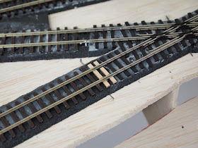
When the track was being installed, ties were cut out for either feeders or track joiners or stuff like that. I started going back and filling these with mock ties. It looks a little funny now as they're practically white next to the dark brown ties, but once the ties and rails are all painted I'm hoping no one will be able to tell the difference. I ended up getting distracted by the next thing though...
I also started building the bridge for the right module. Here it is in an earlier state before final trimming...
And here after it's been stained. I ended up spilling the bottle on it which is why it's really black. I plan to dry brush it white to mellow that out, then go over it with some earth tone weathering powder.
Here are some final shots of the layout. I have enough track down and working that I can actually start doing operations/maneuvers with cars.


No comments:
Post a Comment